This forum uses cookies
This forum makes use of cookies to store your login information if you are registered, and your last visit if you are not. Cookies are small text documents stored on your computer; the cookies set by this forum can only be used on this website and pose no security risk. Cookies on this forum also track the specific topics you have read and when you last read them. Please confirm whether you accept or reject these cookies being set.

A cookie will be stored in your browser regardless of choice to prevent you being asked this question again. You will be able to change your cookie settings at any time using the link in the footer.

Thread Rating:
  • 0 Vote(s) - 0 Average
  • 1
  • 2
  • 3
  • 4
  • 5
ADS1115 reading voltage
#1
Trying to control battery voltage with an ADS1115, (I have OP2 version), Found this problem:

To avoid measuring signals higher than the Vin. (5V in my case), I installed a voltage divider, and really is measuring 3,3V aprox.
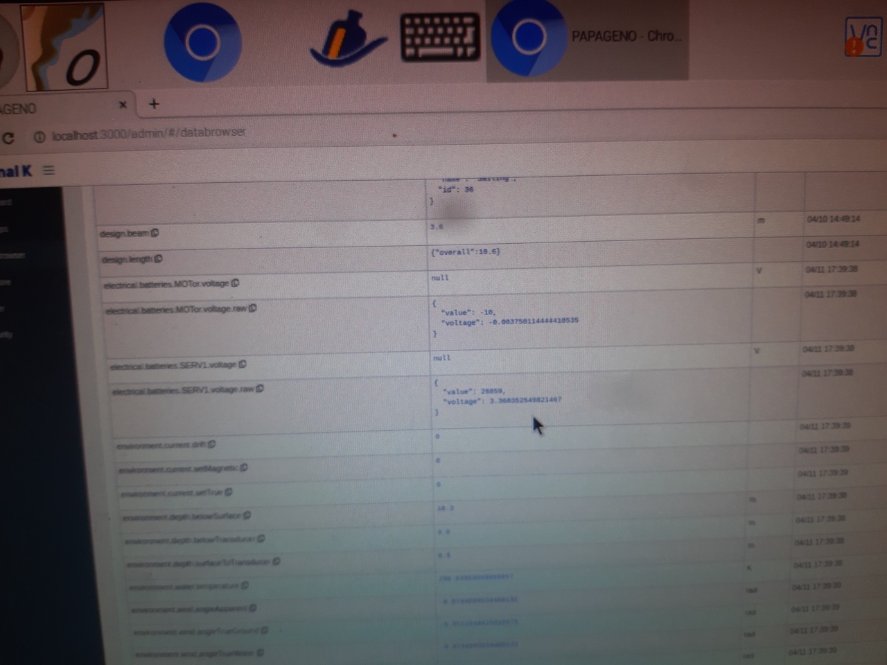
The problem is that se output in SignalK is "null". But is OK if we ask "raw data"

Can anybody aid me to solve this problem?

Many thanks!
       
Reply
#2
It's almost impossible to read the details from photographs. Perhaps you could add a screenshot instead? Your value in electrical.batteries.SERV1.voltage.raw does that say 26859?

When you installed the ADS1115 in I2C what Range did you set?
Reply
#3
I have already discovered the problem. I thought that by powering the ADS1115 at 5v, I could measure a signal up to about 5v. (The limit is VIN+0.3V) and I calculated the voltage divider accordingly.
It looks like the chip actually has a 5 to 3.3v internal step-down, so it can't actually measure signals higher than about 3.6v.

In these conditions, it was somewhat above the range (26,400) and for this reason I was getting a "null" as voltage instead of the actual measurement.

Fixed by modifying the voltage divider R values.

Thanks for the help.
Reply
#4
(2024-04-23, 08:02 PM)SARASTRO Wrote: I have already discovered the problem. I thought that by powering the ADS1115 at 5v, I could measure a signal up to about 5v. (The limit is VIN+0.3V) and I calculated the voltage divider accordingly.
It looks like the chip actually has a 5 to 3.3v internal step-down, so it can't actually measure signals higher than about 3.6v.

In these conditions, it was somewhat above the range (26,400) and for this reason I was getting a "null" as voltage instead of the actual measurement.

Fixed by modifying the voltage divider R values.

Thanks for the help.

The internal gain amplifier is adjustable to 2/3 & can read voltages above 3.3v though not sure if that's `possible in the openplotter setup
Reply
#5
That's interesting, perhaps you have a different type of ADS1115. I power mine from 5V, set gain to 1 (standard in OP) so that maximum voltage it can read is 4.096V and it works fine.


Attached Files Image(s)
   
Reply


Forum Jump:


Users browsing this thread: 1 Guest(s)