This forum uses cookies
This forum makes use of cookies to store your login information if you are registered, and your last visit if you are not. Cookies are small text documents stored on your computer; the cookies set by this forum can only be used on this website and pose no security risk. Cookies on this forum also track the specific topics you have read and when you last read them. Please confirm whether you accept or reject these cookies being set.

A cookie will be stored in your browser regardless of choice to prevent you being asked this question again. You will be able to change your cookie settings at any time using the link in the footer.

Thread Rating:
  • 0 Vote(s) - 0 Average
  • 1
  • 2
  • 3
  • 4
  • 5
Seatalk1 Opto Setup
#1
Seatalk one interface.

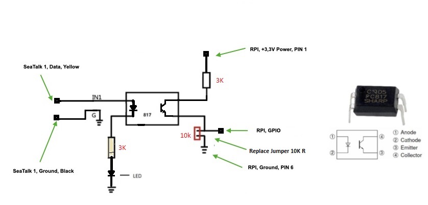
I have noticed there are a lot of different installs of the Seatalk 1 interface, I was not able to get a hold of the board most people are using and found this on on Ebay for a couple of dollars. I didn't have to do much of a modification to get it going other than to replace the on board jumper for a 10 K resistor, and this way I can use the terminal blocks on the board and no external resistors were necessary. The board is shown at the bottom of the page, the LED blinks when the Seatalk data is active. 

This was a simple job and I hope it help make it easy for others. 

                   
Only those who go too far can possibly tell you how far one can go

Our Blog: svmatilda.com
Reply
#2
We are looking into some new wiring to fix some issues with some systems not being able to connect, could you help us by doing an easy test?

Basically you should use the seatalk red and yellow cables instead of the yellow and ground cables:

Current wiring:
- yellow -> +
- ground -> -
- red unused

New wiring:
- red -> +
- yellow -> -
- ground unused

You do not need to make any changes to the raspberry side, just try "inverted signal" yes or no in the settings. This will help us a lot, thank you!
Reply
#3
Hello,

I have done some experimenting and have found that I can get the board working using the red (12V) and the yellow (data) wires.

To do this I could not use this board as is in the photo I had to remove the end of the 10K resistor that shares the common ground on the board. I connected this end of the resistor to the Raspberry Pi pin 6 as in the drawing. If I had left the resistor connected the data line out to the GPIO would have been around 12 volts.

In the set up I did have to Invert the signal

As a side note I did find when I first went to connect and set up Seatalk the Raspberry Pi 3.3 volt line was pulled down by my one wire DS18B20 sensor. I removed the sensor to get enough voltage to make the signal work at the GPIO. I haven’t got back to trouble shoot that however the sensor was still working before i disconnected it.

I mention this just in case those having trouble with communications, should look at the voltage of the line to the opto board for the signal to GPIO.

I also tried the board as they come with no modification and I could not get it to work with the signal inverted or not.
Only those who go too far can possibly tell you how far one can go

Our Blog: svmatilda.com
Reply
#4
OK, that was really useful, thanks!!!
Reply


Forum Jump:


Users browsing this thread: 1 Guest(s)