This forum uses cookies
This forum makes use of cookies to store your login information if you are registered, and your last visit if you are not. Cookies are small text documents stored on your computer; the cookies set by this forum can only be used on this website and pose no security risk. Cookies on this forum also track the specific topics you have read and when you last read them. Please confirm whether you accept or reject these cookies being set.

A cookie will be stored in your browser regardless of choice to prevent you being asked this question again. You will be able to change your cookie settings at any time using the link in the footer.

Thread Rating:
  • 0 Vote(s) - 0 Average
  • 1
  • 2
  • 3
  • 4
  • 5
DIY Linear Actuator -- photos
#1
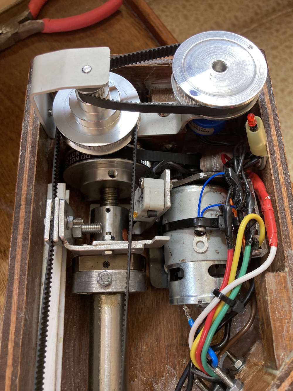
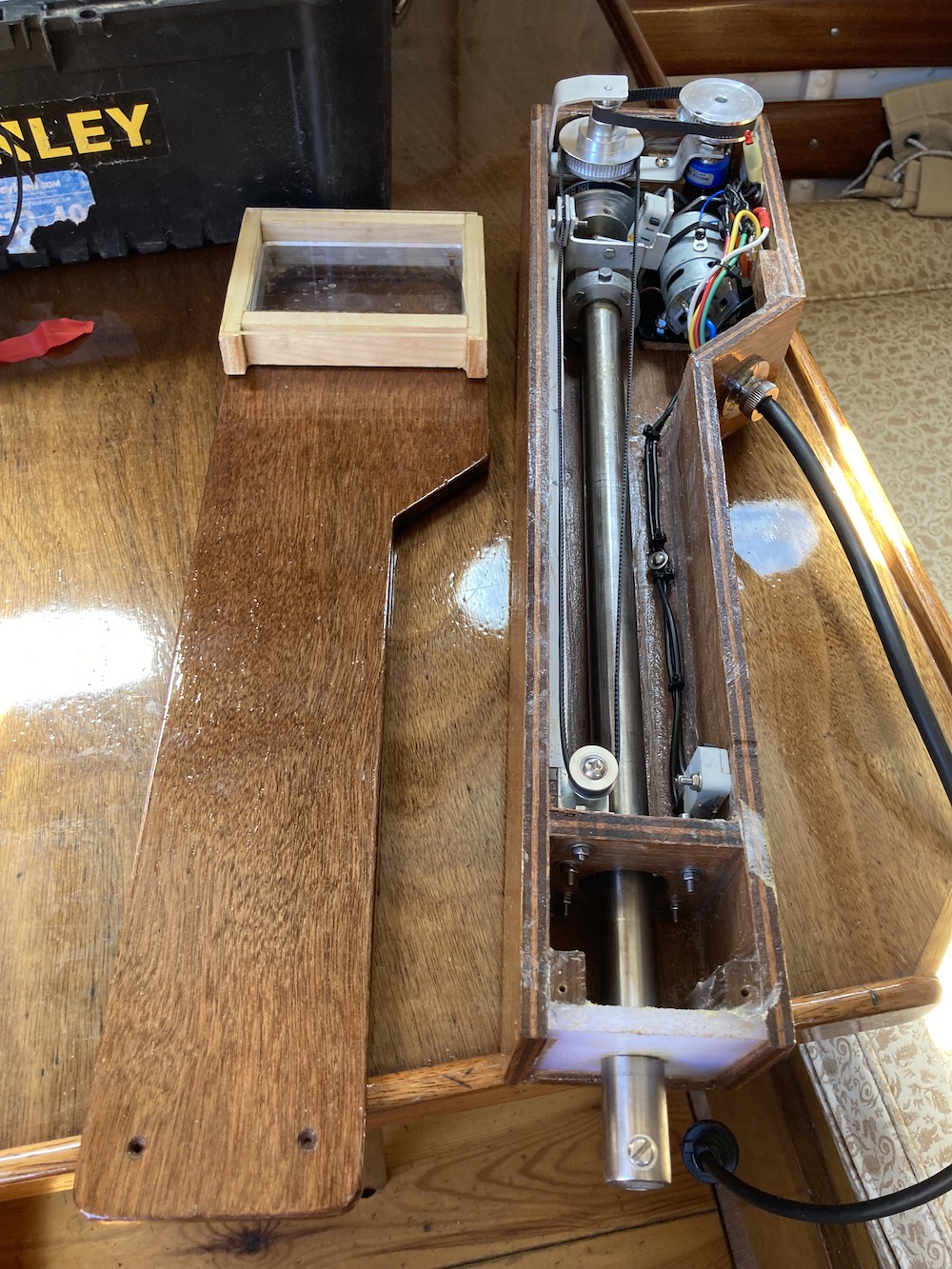
What with all the faff of trying to find a suitable Linear Actuator for pypilot, I decided to make one instead.  

The motor is an RS 550. The ball screw is an inexpensive one from Amazon. The stroke is 300mm and even at 50% power it travels that distance in about three seconds.

It's bigger and heavier than I'd envisaged, but it's pretty robust, and if something goes wrong with it, I'll hopefully know how to fix it. Cheers!        

Attached Files Image(s)
   
Reply
#2
I love it! Suits the boat as well!
Reply
#3
This is really great to see!

I have tried those ball screws and found they rust easily. My understanding is they are using 400 series alloy rather than the 316 variety. We would be better served with 316 since the load is not that high. In any case I would keep lots of grease on it and ensure the box remains water (and as airtight) as possible.

If water enters in the siding seal, does it drain back out? Do you think it would make sense to use even smaller belts on the rudder feedback? How much backlash is there?

My favorite actuator moves 150mm/s. This is most useful at higher speeds and surfing waves. It is easy to make it move slower by changing some settings in pypilot for lightwind.

do the end stop switches engage in time? Do you need to add a spring or something?
Reply
#4
(2023-08-10, 01:56 PM)ironman Wrote: I love it! Suits the boat as well!

Thanks! It was pure luck that the ply turned the same colour as my iroko boat after a bit of varnish.

(2023-08-10, 03:18 PM)seandepagnier Wrote: This is really great to see!

I have tried those ball screws and found they rust easily.  My understanding is they are using 400 series alloy rather than the 316 variety.  We would be better served with 316 since the load is not that high.  In any case I would keep lots of grease on it and ensure the box remains water (and as airtight) as possible.

If water enters in the siding seal, does it drain back out?  Do you think it would make sense to use even smaller belts on the rudder feedback?  How much backlash is there?

My favorite actuator moves 150mm/s.  This is most useful at higher speeds and surfing waves.    It is easy to make it move slower by changing some settings in pypilot for lightwind.

do the end stop switches engage in time?  Do you need to add a spring or something?

Thanks Sean

I'm afraid to say my ball screw isn't stainless at all (couldn't find one the right length that didn't have to be posted from China) so yeah I'll be greasing it regularly. 

As for water ingress the ram goes through two holes a few cm apart and I'm hoping not much water will make it past this antechamber. I'll drill a weep hole in the floor if necessary. Again, I'm banking on lots of grease.

As for backlash ... there's a bit of play in the feedback mechanism at the moment, maybe 2mm at the rim of the potentiometer wheel, but I'm hoping that tightening the belts will eliminate most of it. They're way too slack.

And finally, the limit switches don't remotely stop the motor in time so you're right, I really should add some springs. But these are really just an ultimate fail-safe if for some reason the rudder sense doesn't do its thing.

Cheers!
Reply
#5
what if you used hall sensors or reed switches and a magnet for the stop switches? This way there is never any contact and it cant break the switch...

Another thing is to add springs or something so if the switch or rudder feedback doesnt work, the overcurrent limit will not be as much of a crash. I have a rope preventing it from going out too far and it squeeze a rubber thing if it moves in too close.

I dont think water will be too much of a problem but will be interesting to see. The tighter of a seal you make on a sliding arm the more energy is wasted in friction, so I think it may be best to not have a perfect seal and do what you have, multiple holes and this "antechamber"

How did you determine the belt ratio? Are you sure it is the best one to use?

As for backlash in the rudder feedback I wouldnt worry about this too much, since its only used to prevent end of travel with the basic pilot.
Reply
#6
(2023-08-11, 03:49 AM)seandepagnier Wrote: The tighter of a seal you make on a sliding arm the more energy is wasted in friction

I did buy a proper oil seal for it, but it was way too tight. I suspect they're for applications where friction isn't an issue.

Anyway, yesterday I spent a few minutes pouring water onto the ram while moving it in and out, and as I'd hoped I got a little puddle of water in the antechamber but almost nothing in the main chamber. Realistically, if I used it in the pouring rain for hours I'd open it up afterwards and dry it out.

The belt ratio was simply the highest I could achieve with a single belt -- 12t to 80t, or 1:6.66. I couldn't find any reliable specs for the motors I bought on Amazon. One claimed to be 22,000 rpm which I thought was too high, so I bought another which claimed to be 8,000 rpm and as far as I could tell received the same motor. But with the servo.speed.max slider at 50% at I'm getting roughly 100mm per second, and at 100% it's roughly 150mm per second. (That's with it attached to the tiller.) So far it's coped with a bit of weather helm but I haven't tried it in really challenging conditions yet. For the moment this ratio seems to be working. It's worth saying that even after prolonged use on a hot day the motor barely gets warm.

BTW I remember you wondering if a tiller might back-drive a ball screw, but while this does happen to the ball screw in isolation, once it's hooked up to the motor at this sort of ratio I think it'd be impossible.
Reply
#7
For some reason, seeing the DIY approach really helps me visualize and understand better how linear actuators work. Kudos. Would you be willing to post a parts list with links for the ball screw, motor, and gears you used? What's that little blue thing in the top right corner?

On the backdrive question, it looks like you've essentially clamped the belt with metal bits and a bolt to have it drive the screw forward and back. Would it be feasible to convert that to some kind of solenoid clamp (maybe someone has the better terminology) and hook that into the logic of the pilot so it would freewheel when on standby?
Reply
#8
The belt does not drive the screw - the screw drives the belt that is connected to the potentiometer - the blue thing. This potentiometer measures the absolute position of the screw - for feedback purposes. The ball screw is driven by the motor: only the two gears that rotate in the vertical plane.
Reply
#9
cool i have a few ball screws that i am going to build a cnc out of thanks for sharing..
i love the diy.
Reply


Forum Jump:


Users browsing this thread: 1 Guest(s)