Posts: 219
Threads: 28
Joined: Jul 2020
Reputation:
10
2024-03-27, 06:23 PM
(This post was last modified: 2024-03-27, 06:23 PM by MigGat.)
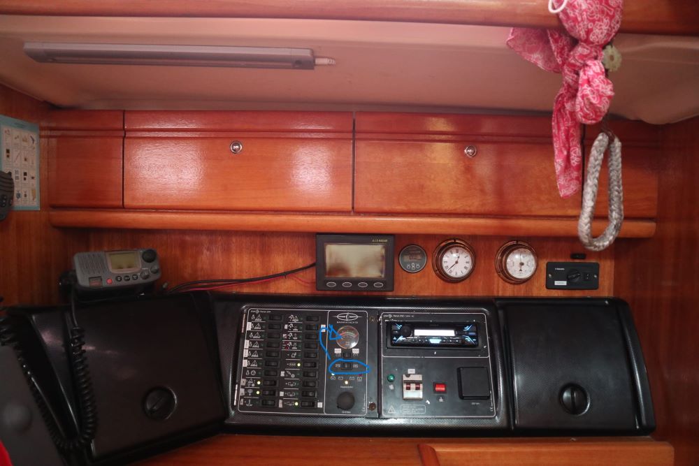
Hello everyone. On the electrical panel of my boat, there's the tipical gauge which can display both batteries voltage.
But it also can display the level on the 2 water tanks. Behing the panel there's a board with several connections (I assume 2 of them are from analogical sensors coming from the tanks).
Is there a way, probable using SensESP or similar, to put that info into SignalK?
Thanks!

Posts: 159
Threads: 14
Joined: Oct 2020
Reputation:
4
Short answer, yes, definitely. You have a BMV there, so are you using a CerboGX? That'd be a pretty easy way to digitize tank/voltage data and get it into SK.
Posts: 219
Threads: 28
Joined: Jul 2020
Reputation:
10
The BMV is connected to the raspberry directly using a a V.E. Direct cable, connected through USB. As well as the solar charger, which uses another VE Direct cable. As far as I know there is no Cerbo GX installed but i haven't discovered all the electrical bits on this boat yet.
So tomorrow I'll check all that out and also I'll take pictures of what's inside the electrical panel, maybe there are some hints there.
Thanks SCarns, you got me started! 
Posts: 1,220
Threads: 102
Joined: Mar 2016
Reputation:
72
Would be useful to measure the voltage on the tank wires.
Also, signalk can now read victron data over bluetooth if you need to free up USB connection into the Pi. Pi3 is very slow but works well with a Pi4
Posts: 219
Threads: 28
Joined: Jul 2020
Reputation:
10
2024-03-28, 05:08 PM
(This post was last modified: 2024-03-28, 05:11 PM by MigGat.)
Thanks PaddyB for the tips on Victron and Bluetooth-
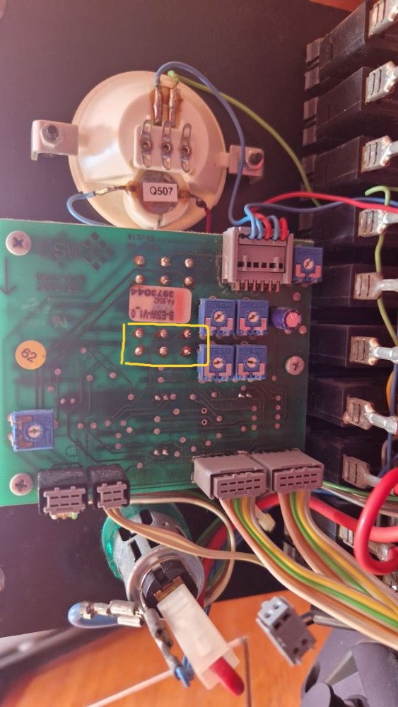
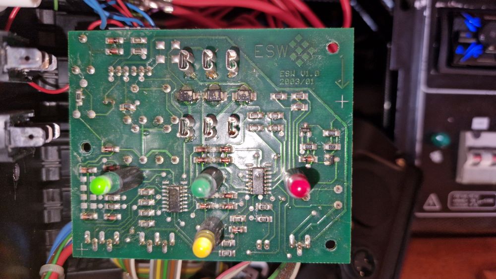
This is what lies behind the electrical panel:


Both tanks are completely full now. The house battery voltage is around 13.82V.
When the swith is "idle" or let's say in the center position, the voltage is 6.64V:

When I press the switch to one side (the one i'm measuriing with the multimeter), the voltage is -0.430V:

Do these number make sense?
Posts: 159
Threads: 14
Joined: Oct 2020
Reputation:
4
If you have the USB Victron connectors, that is a very easy way to go to get data into SK.
As for the tank sensors, that's a different story. You'll need something to take the measurements, read the data and then (possibly) use the calibration plugin to make the adjustments. If you go the SensESP route, you can do this. The numbers don't really mean anything to me, but the difference between the numbers at "full" and "empty" are what will matter.
There's a bunch of different ways to do this. On my boat, I found it easiest to use an Alba Combi ( https://www.albacombi.com) to digitize tank and engine data. On my old boat I built a capacitive sensor with SensESP which worked great, too. You'll need some way to read the sensor at full (1.0) & empty (0.0) and adjust for in-between (0.1-0.9).
Posts: 219
Threads: 28
Joined: Jul 2020
Reputation:
10
Yes yes, Victron has been working for a while now with the cables. No problem on that side.
For the tanks, i think i'm gonna go with SensESP, because is what i know best, so i'll just write the program, and monitor the voltage for some time while I empty one of the tanks. Not sure yet, AlbiCombi seems quite cool, and a way to centralize all these sensors, so i might as well go for it.
Regarding the engine, which is quite important for me too, I opened this other thread: https://forum.openmarine.net/showthread.php?tid=5289
I'm gonna post pictures of the engine electronics now, to see if they can be of any help.
Posts: 219
Threads: 28
Joined: Jul 2020
Reputation:
10
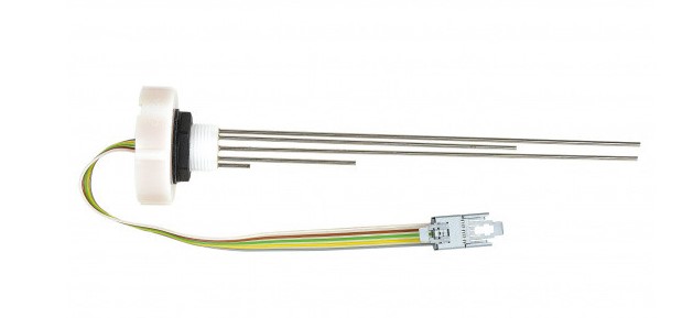
So I found out this is the kind of sensor the tanks have:

That explains why it only displays 0%, 25%, 50%, 75% and 100%, and no other value in between, which well, let's say it's suboptimal at the very best.
Posts: 219
Threads: 28
Joined: Jul 2020
Reputation:
10
I found this diagram and I understand now how it works:

So I think I could connect all both Com. wires to ground, and the other 8 wires to ESP32 inputs.
However, I in order to do that I need to "duplicate" the connector so on one side stays connected to the electrical panel, and the other to the ESP32. But I don't know how this connector is called, so I don't know how to buy a "duplicator" (or splicer, or however this is called).
Any inputs on that?
|


